Documentation
For the brake part, there really wasn't much "idea" to it since the design was given to us. However I still had to be creative enough to create the design into an Inventor file give the constraints. Then I created my tool-paths in Fusion 360. And then I made it come to life in the CNC Mill.
Brake Part "Recipe"
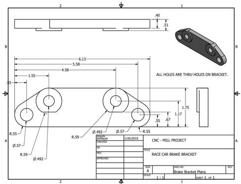
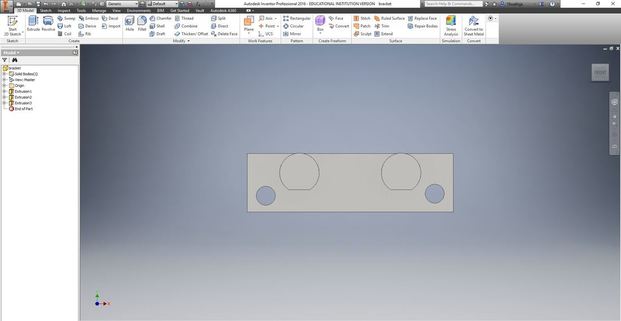
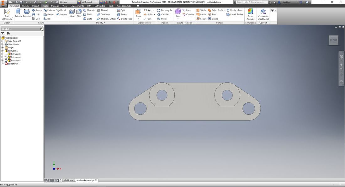
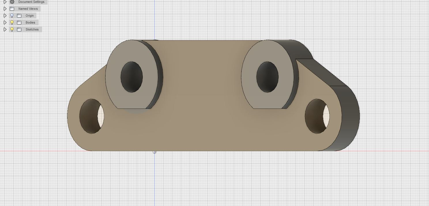
To create the brake part, first you have to view the provided design. Study the design and create the base of it in Inventor. Then sketch and extrude the individual parts of the brake part keeping in mind the constraints. Once it's created make sure the part matches up with the original provided diagram. Then move it into Fusion 360 and create the tool-paths. Once it is ready, set it up on the CNC Mill and watch it form into your brake part!
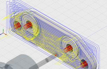
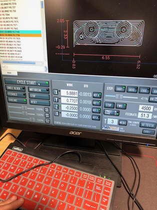
Project Screenshots
|
|
Physical Images
|
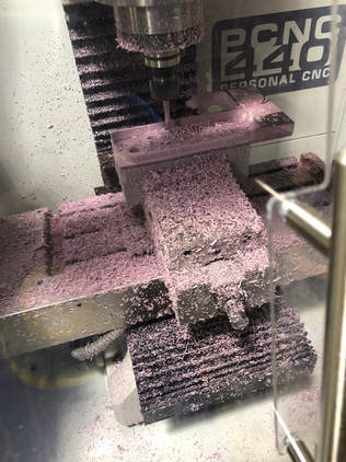
|
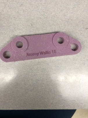
Final Brake Part
Summary
For the CNC Mill I learned that it might be the most confusing looking machine due to the large number of options in the program set-up. Luckily for our project we only had to do a couple of things to set it up, but there are so many different options you can use when using it, it just seems very overwhelming. I must say I wasn't a huge fan of the mill, it might have just been because the project wasn't our original creation.
